


| next newest topic | next oldest topic |
| Author | Topic: free volume - TS extruder |
|
parag_natu Member Posts: 4 |
  
Hallo, I am working on project which deals with optimisation of cleaning/purging process on ZSk 92. For the same reason, I am in need of information of free volume with 2 lobed elements (screw elements, kneading blocks..all are 2 lobed). How can one calculate the free volume?? Free volume = volume of cylinder block - volume of screw. But....how can I calculate each of them?? Please give info about the formulae .... warm regards, IP: Logged |
|
Tom C Moderator Posts: 974 |
Try searching the internet for papers on determining the residence time in thwin screws. The volume is required for that calculation. Fortunatly the cross sectional area for standard screw elements and kneading blocks is the same, so one only needs to find the open area and multiply it by the length. Undercut elements, SME, TME, ZME, Tri-lobe and other such specialy elements require different calculations. I've had good results using 1MI HDPE to purge with on these machines. Fiberglass can be added to the mix for extra cleaning action. ------------------ Tom Cunningham www.ExtrusionTechnicalServices.com IP: Logged |
|
parag_natu Member Posts: 4 |
first of all...thanx Do you have any formule with which I can calculate the cross sectional areas of screw element? I have 2 formulae but...they are not properly working on my values.... 1) cross sectional area of cylinder = 2[(Dz*Dz*Sin(2▀z)/8)+(Dz*Dz*(pi-▀z)/4)] 2) cross sectional area of screw = 2i[(Dd*Sin(theta)/8)+((D*D+d*d)*alpha/16)+(Ath*Ath/2*(theta/2-sin(theta/2))] Free cross sectional area = (1) - 2*(2) free volume = free area * Length of screw. but..these are not working. I refferred one book...but...???? do you have such formule, by which I can calculate the areas..... another question...for ZME....can I use water immersion (water displacement) method? how exactly will this method function? IP: Logged |
|
parag_natu Member Posts: 4 |
and thanx for your advice with HDPE..with or without glass filled... I am currently trying out with LDPE with and without glass filled... IP: Logged |
|
Tom C Moderator Posts: 974 |
This is courtesy of Charlie Martin of American Leistritz; 5. Specific volume Specific volume (SV) represents the approximate volume per screw outside diameter (OD) length of screws for traditional Erdmenger-type screw geometries. This calculation, which is useful in a number of other formulas, allows you to calculate the volume in the process section. SV is calculated as follows: Specific volume=.94 x (OD2-ID2) x OD/1000 SV is denoted in cc/diameter of length (itÆs always best to obtain SV data from the machine supplier, if possible),
SV=.94 x (502-322) x 50/1000 = 73.8 cc/dia This number can also be used for rough scaling between different size machines that share geometric similarities (OD/ID ratio) and that are not too dramatically different in size. For instance: Qtarget=Qreference x (volumetarget/volumereference) For example, if a 45-mm twin-screw extruder has a SV of 60 cc/dia and is running at 150 kg/hr then it can be inferred that a 75-mm extruder with a SV of 240 cc/dia will process approximately four times the rate: Qtarget (75 mm) = 150 x (240/60)=600 kg/hr 6. Fill % approximation This formula provides the percentage of the available volume in the process section that is being utilized in the starved-fed HSEI twin-screw extruder. This calculation is useful to approximate a starting point as to where to run a process. The following formula can be used: % fill = (Q x .2777)/(SV x rpm/60) x (SG x Ef)
% fill = (50 x .2777)/[34.8 x (200/60)] x 1 x .35= .34, or 34% filled This formula is a very rough estimation and is meant to provide some insight into the dynamics of a starved process section. More advanced/accurate calculations take into account the specific screw geometries, the viscosity of the melt, and the degree of screw fill. This calculation might show that devolatilization intensive processes run at 30% (or less) screw fill because a highly starved process section increases the surface area of the melt pools under the vent. Another example could demonstrate that similar masterbatch formulations for film/fiber applications utilize a 40% volume, compared to 60% for injection molding applications, because of the comparative dispersive mixing requirements. Higher fill levels result in a tighter residence time distribution (RTD) and less shear, and lower fill levels are associated with wider RTD and more shear. Fill level approximations help explain why different processes benefit from comparative fill level percentages. 7. Residence time This formula provides the approximate residence time (RT) in the process section of an HSEI twin-screw extruder. As denoted above, the residence time distribution is highly dependent upon the degree of screw fill. The following formula can be used for RT: RT(sec) = (SV x SG x L/D x %fill)/(Q x .2777)
RT = (70cc/dia x 1.1 x 48 x .4)/(270 x .2777) The RT formula provides insight as to how long materials are exposed to heat and shear in the process section. 8. Specific throughput The specific throughput (ST) provides the output per rpm for a given process and can be calculated as follows: ST=(kg/hr)/rpm For example, if a 100-mm twin-screw extruder is successfully processing a formulation at 1000 kg/hr with 250 rpm, this equates to 4kg/rpm. ST=1000/250= 4kg/rpm Specific throughput provides a number that is proportional to the degree of fill and is used to process similar products at different rates on the same machine. For instance, if a product runs at 1000 kg/hr at 250 rpm, then for 2000 kg/hr on the same extruder 500 rpm is a good starting point. ST is often helpful to scale-up/down products on different size extruders, in that over time a process that runs 5 kg/hr on a 30-mm class machine will most likely equate to 50 kg/hr (or another rate) on a 60-mm class machine, and vice versa. ------------------ Tom Cunningham www.ExtrusionTechnicalServices.com IP: Logged |
|
Tom C Moderator Posts: 974 |
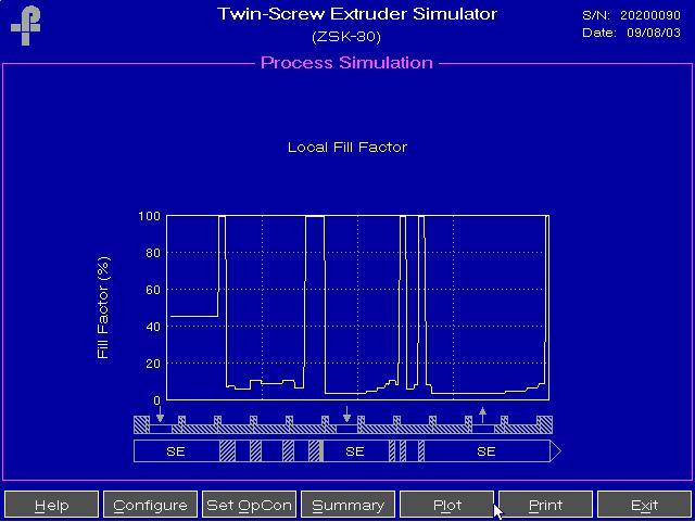
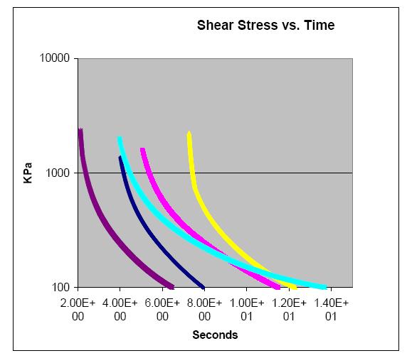
I was interested iin your purging analysis, so I have some items to add. Much more analysis can be done, but here are some thoughts. The above is a graph of typical fill factor levels in a twin screw. Twin screws are run starve fed, so the channels are not full. I'm not sure a partially filled channel will purge much at all. or perhaps only the pushing side of the flights.
Good purging of screw and barrel surfaces need a combination of high viscosity, high shear rates and surface contact in order to clean well. This is a difficult combination to get in a co-rotating twin screw extruder.
------------------ Tom Cunningham [This message has been edited by Tom C (edited May 19, 2006).] [This message has been edited by Tom C (edited May 20, 2006).] [This message has been edited by Tom C (edited May 20, 2006).] [This message has been edited by Tom C (edited May 20, 2006).] IP: Logged |
|
Tom C Moderator Posts: 974 |
Sorry, the pictures were working. I'll try and fix it. ------------------ Tom Cunningham www.ExtrusionTechnicalServices.com IP: Logged |
|
parag_natu Member Posts: 4 |
Thanx for the information .... I will be waiting eagerly for those pictures/graphs..without which...those terms like extra polation and all other are difficult to understand... regards, IP: Logged |
|
nakulbende Member Posts: 1 |
Hello, I am a student at IIT roorkee. I searched for the source of these equations but haven't found any research paper/ journal/ book in which these are published. Could somebody please help me with this. I need the reference to present my work. IP: Logged |
|
Tom C Moderator Posts: 974 |
Look for papers by: Potente ------------------ Tom Cunningham www.ExtrusionTechnicalServices.com IP: Logged |
All times are ET (US) | next newest topic | next oldest topic |
  |
|
Contact Us | Feed Screw Designs
Powered by Infopop www.infopop.com © 2000
Ultimate Bulletin Board 5.45a